前言
此篇文章为有关 ESP32 的学习期间的代码记录,并且加上了自己的注释,非教学文章。
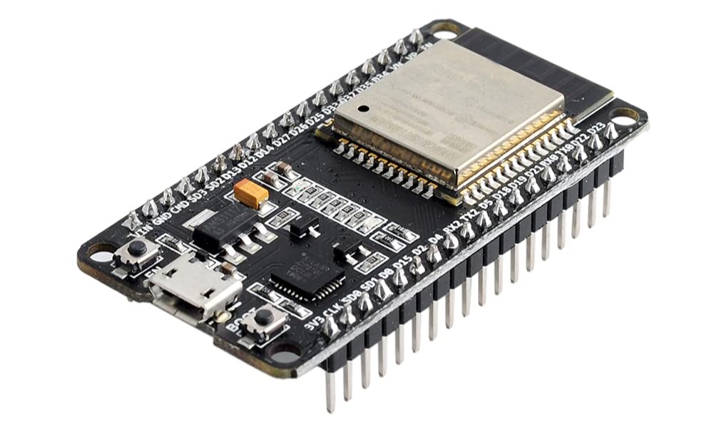
使用开发板全称ESP32 DEVKILTv1(devkitv1) ,搭载芯片为 ESP32D0WDQ6,使用软件为 Arduino 。
参考链接
如果是小白并且想要学习单片机相关知识,建议移步此篇文章:51单片机入门教程(上篇)(代码+个人理解) – Echo (liveout.cn)
此篇文章参考教程视频:小鱼创意的个人空间哔哩哔哩bilibili
GitHub代码样例链接:https://github.com/PGwind/ESP32code
开发板详细讲解:ESP32 DEVKILTv1(devkitv1)开发板全解析
1. 点亮LED
1.1 点亮第一个LED
int ledPin = 2; //定义引脚,一般为板载蓝色灯

void setup() {
  // put your setup code here, to run once:
  pinMode(ledPin,OUTPUT); //输出模式
}

void loop() {
  // put your main code here, to run repeatedly:
  digitalWrite(ledPin, HIGH); //引脚高电平,即等效于 digitalWrite(ledPin, 1);
}
1.2 LED闪烁
int ledPin = 2;

void setup() {
  pinMode(ledPin,OUTPUT);

}

void loop() {
  digitalWrite(ledPin, HIGH);
  delay(2000); //延迟
  digitalWrite(ledPin, LOW);
  delay(2000);
}
1.3 不同闪烁周期LED
int ledPin2 = 2;
int ledStatus2 = 0;  //现在的状态
unsigned int prevTime2 = 0; //改变状态时的时间

int ledPin4 = 4;
int ledStatus4 = 0;
unsigned int prevTime4 = 0;

void setup() {
  pinMode(ledPin2, OUTPUT);
  digitalWrite(ledPin2, HIGH);
  ledStatus2 = HIGH;
  prevTime2 = millis(); //millis(): 本程序已经运行的时间(ms) micros()微秒us

  pinMode(ledPin4, OUTPUT);
  digitalWrite(ledPin4, HIGH);
  ledStatus4 = HIGH;
  prevTime4 = millis(); //millis(): 本程序已经运行的时间(ms) micros()微秒us
}

void loop() {
  unsigned int now = millis(); //程序运行的时间

  if (now - prevTime2 > 3000) //上次改变状态后已经过了3s
  {
    int status  = ledStatus2 == HIGH ? LOW: HIGH;
    digitalWrite(ledPin2, status);
    ledStatus2 = status;
    prevTime2 = now;
  }

  if (now - prevTime4 > 1000) //上次改变状态后已经过了1s
  {
    int status  = ledStatus4 == HIGH ? LOW: HIGH;
    digitalWrite(ledPin4, status);
    ledStatus4 = status;
    prevTime4 = now;
  }
}
2. 按键
2.1 按键控制LED
int switchPin = 25; //按键所接GPIO口
int ledPin = 4; //LED接口
int ledStatus = 0; //LED目前状态

void setup() {
  pinMode(switchPin, INPUT_PULLUP);//INPUT_PULLUP上拉,低电平有效,检测到低电平表明按键已经按下
  pinMode(ledPin, OUTPUT);
  digitalWrite(ledPin, HIGH);
  ledStatus = HIGH;
}

void loop() {
  int val = digitalRead(switchPin); //读取开关引脚的电平状态
  if (val == LOW) //低电平有效
  {
    ledStatus = !ledStatus;
    digitalWrite(ledPin, ledStatus);
  }
}
2.2 软件消除抖
使用 RBD_ Button 库进行消抖,在 库管理 处进行安装
#include <RBD_Timer.h>
#include <RBD_Button.h>

int switchPin = 25;
int ledPin = 4;
int ledStatus = 0;

//创建一个可以消除拉动的按键对象
RBD::Button button(switchPin, INPUT_PULLUP);

void setup() {
  pinMode(ledPin, OUTPUT);
  button.setDebounceTimeout(20); // 消除抖动时间是20ms
}

void loop() {
  //检测按键按下去的事件(下降沿)
  if (button.onPressed()) //按键已经按下
  {
    ledStatus = !ledStatus;
    digitalWrite(ledPin, ledStatus);
  }
}
3. PWM
LED控制(LEDC)外围设备主要用于控制LED的强度,尽管它也可以用于生成PWM信号用于其他目的。它具有16个通道,可以生成独立的波形,这些波形可以用于驱动RGB LED器件。
3.1 LEDC(PWM)
void setup() {
  int ret = 0; //状态
  Serial.begin(115200);
  int ch0 = 0; //通道
  int gpio4 = 4; //引脚
  ret = ledcSetup(ch0, 5000, 12); //设置ledc通道0,频率5000HZ,精度12

  delay(200);
  if (ret == 0)
    Serial.println("Error Setup");
  else
    Serial.println("Success Setup");

  ledcAttachPin(gpio4, ch0); //设置引脚和通道
  ledcWrite(ch0, pow(2, 11)); //占空比50%   2^11 / 2^12 = 1/2

}

void loop() {
  // put your main code here, to run repeatedly:

}
3.2 LED呼吸灯
每秒钟固定调整占空比 50 次。 T 为呼吸周期,光从灭到最亮经过半个周期T/2。
半个周期进行 50*T/2 调整占空比
count 表示占空比为 100% 时等分的格子
step 为每次调整时要加上的增量 step = count / (50 * T/2) = 2 * count / (50 * T)
3.2.1 使用 delay() ,呼吸周期偏长
/* 每秒钟固定调整占空比50次。T为呼吸周期,光从灭到最亮经过半个周期T/2。
   半个周期进行 50*T/2 调整占空比
   count表示占空比为100%时等分的格子
   step为每次调整时要加上的增量  step = count / (50 * T/2) = 2 * count / (50 * T)
*/

int gpio4 = 4;
int ch1 = 1; //ledc通道号
int duty = 0; //目前信号的占空比
int count = 0; //100%占空比时的格子
int step = 0; //占空比步进值(增量)
int breathTime = 3; //呼周期,单位s

void setup() {
  ledcSetup(ch1, 1000, 12); //建立ledc通道
  count = pow(2, 12); //计算占空比为100%时共几份
  step = 2 * count / (50 * breathTime); //计算一次增加多少格子
  ledcAttachPin(gpio4, ch1); //绑定 ch1 和 GPIO4
}

void loop() {
  ledcWrite(ch1, duty);
  duty += step;
  if (duty > count)
  {
    duty = count;
    step = -step; //step变为负数,duty递减
  }
  else if (duty < 0)
  {
    duty = 0;
    step = -step; //step变为正数,duty递增
  }
  delay(20); //阻塞20ms
}
3.2.2 使用 millis
int prevTime = 0;
int gpio4 = 4;
int ch1 = 1; //ledc通道号
int duty = 0; //目前信号的占空比
int count = 0; //100%占空比时的格子
int step = 0; //占空比步进值(增量)
int breathTime = 3; //呼周期,单位s

void setup() {
  ledcSetup(ch1, 1000, 12); //建立ledc通道
  count = pow(2, 12); //计算占空比为100%时共几份
  step = 2 * count / (50 * breathTime); //计算一次增加多少格子
  ledcAttachPin(gpio4, ch1); //绑定 ch1 和 GPIO4
}

void loop() {
  int now =  millis();
  if (now - prevTime >= 20) //上次改变状态后已经过了 20ms
  {
    ledcWrite(ch1, duty);
    duty += step;
    if (duty > count)
    {
      duty = count;
      step = -step;
    }
    else if (duty < 0)
    {
      duty = 0;
      step = -step;
    }
    prevTime = now;
  }
}
4. 软件定时器
使用 AsyncTimer 库进行定时操作,在 库管理 处进行安装。
定时器主要模式:
- 等待多长时间触发一个事件
- 每个多久时间触发一个事件
- 到某个时间点触发一个事件
定时器类型:
- 硬件定时器:ESP32只有4个
- 软件定时器:精度低,数量多
4.1 单次定时任务
串口定时打印信息
#include <AsyncTimer.h>

AsyncTimer t; //定义一个定时器

void myfun()
{
  Serial.println("the second");
}
void setup() {
  Serial.begin(115200);
  delay(200);

  //setTimeout(回调函数, 超时时间(ms)),回调函数可以无参无返回值
  auto id = t.setTimeout([](){ //第一个单次定时任务:2s 打印 the first
    Serial.println("the first");
  }, 2000);
  Serial.print("First:");
  Serial.println(id);

  id = t.setTimeout(myfun, 4000); //第二个单次定时任务:4s 打印 the second
  Serial.print("Second:");
  Serial.println(id);
}

void loop() {
  t.handle(); //执行有关定时器的操作,精度与loop()函数里面操作时间有关
}
First:62510
Second:36048
the first
the second
4.2 周期定时任务
#include <AsyncTimer.h>

AsyncTimer t;

void myfun()
{
  Serial.println("the second");
}

void setup() {
  Serial.begin(115200);
  delay(200);

  //setInterval(回调函数, 超时时间(ms)),回调函数可以无参无返回值
  auto id = t.setInterval([](){ //第一个周期定时任务:每 2s 打印 the first
    Serial.println("the first");
  }, 2000);
  Serial.print("First:");
  Serial.println(id);

  id = t.setInterval(myfun, 4000); //第二个周期定时任务:每 4s 打印 the second
  Serial.print("Second:");
  Serial.println(id);
}

void loop() {
  t.handle();
}
the first
the first
the second
4.3 闪烁LED改造
LED灯刚启动以1s周期进行闪烁,按键按下去后在1s和3s的周期进行切换
// LED灯刚启动以1s周期进行闪烁,按键按下去后在1s和3s的周期进行切换
#include <RBD_Button.h>
#include <AsyncTimer.h>

int switchPin = 25; // 按钮
int ledPin = 4; // led
int ledStatus = HIGH;
int t = 1; // 闪烁周期

// 软件消抖
RBD::Button button(switchPin, INPUT_PULLUP);

AsyncTimer timer;
int taskId = 0;

void ChangeLedStatus() // 改变LED状态函数
{
  ledStatus = !ledStatus; // 状态取反
  digitalWrite(ledPin, ledStatus); // 改变状态
}

void setup() {
  pinMode(ledPin, OUTPUT);
  digitalWrite(ledPin, HIGH); // 点亮
  button.setDebounceTimeout(20);
  // 创建周期任务
  taskId = timer.setInterval(ChangeLedStatus, t*1000);
}

void loop() {
  timer.handle();

  if (button.onPressed())
  {
    t = t == 1?3:1; // 周期定时时间为:1s或3s
    timer.changeDelay(taskId, t*1000);
  }
}
4.4 相关函数讲解
停止单个定时任务:
cancel(intervalOrTimeoutId),intervalOrTimeoutid即定时任务的编号停止多个定时任务:
cancelAll(includeIntervals),参数默认值为true。true:取消所有定时任务 fasle:只取消单次定时任务
改变定时任务周期:
changeDelay(intervalOrTimeoutId, delaylnMs),参数分别为定时任务的编号 和 新的超时时间(ms)重置定时任务:
reset(intervalOrTimeoutId),只能重置还没有停止的定时任务,重置完从0重新计时额外延时一个定时任务:
delay(intervalOrTimeoutId, delaylnMs),参数分别为定时任务的编号 和 额外延时时间(ms)获取定时任务剩余时间:
getRemaining(intervalOrTimeoutId),获取指定定时任务本轮还剩多久时间超时unsigned long remaining = getRemaining(timeoutId);
5. ADC模数转换
5.1 样例
void setup() {
  Serial.begin(115200);
  analogReadsolution(12); // 设置读取精度(位宽)

  //设置通道衰减值(不设置默认为11db)
  /*
  analogSetAttenuation(ADC_ATTEN_DB_11); // 设置所有通道
  analogSetPinAttenuation(2, ADC_ATTEN_DB_11); // 设置指定GPIO口的衰减值
  */
}

void loop() {
  int analogValue = analogRead(2); // 读取DAC值
  int analogVolts = analogReadMilliVolts(2); // 读取电压值(c)

  Serial.printf("ADC analog value = %d\n", analogValue);
  Serial.printf("ADC millivolts value = %d\n", analogVlots);

  delay(100);
}
5.2 电位器控制LED亮度
/* ADC + LEDC + 定时器(软件)
  通过更改定位器阻值控制LED亮度
*/
#include <AsyncTimer.h>

int pmPin = 32; // 电位器GPIO接口
int ledPin = 4; // LED
int ch0 = 0; // ledc通道

AsyncTimer timer;
int taskId = 0;

void ChangeLedLightness()
{
  int val = analogRead(pmPin);
  Serial.printf("%d:", val);

  auto vol = analogReadMilliVolts(pmPin);
  Serial.println(vol);

  int duty = val / 4095.0 * 1024;
  ledcWrite(ch0, duty);
}

void setup() {
  Serial.begin(115200);
  analogReadResolution(12); // 确定analogRead() 函数返回的值的分辨率(以位为单位)
  analogSetAttenuation(ADC_11db); // 设置所有通道衰减值

  ledcSetup(ch0, 1000, 10); // 设置ledc通道0,频率1000HZ,精度10
  ledcAttachPin(ledPin, ch0);

  taskId = timer.setInterval(ChangeLedLightness, 20); //周期定时任务
}

void loop() {
  timer.handle();
}
6. I2C协议
6.1 I2C及Wire库使用
主机
// 主机Master
#include <Wire.h>

#define I2C_DEV_ADDR 0x55  // I2C设备地址

uint32_t i = 0;

void setup() {
  Serial.begin(115200);
  Serial.setDebugOutput(true); // 启用串口调试输出
  Wire.begin(); // 初始化I2C总线
}

void loop() {
  delay(5000);

  Wire.beginTransmission(I2C_DEV_ADDR); // 开始I2C传输
  Wire.printf("Hello World! %u", i++); // 向I2C设备发送数据
  uint8_t error = Wire.endTransmission(true); // 结束I2C传输并检查错误
  Serial.printf("endTransmission:%u\n", error);

  uint8_t bytesReceived = Wire.requestFrom(I2C_DEV_ADDR, 16); // 从I2C设备读取数据并返回接收到的字节数
  Serial.printf("requestFrom:%u\n", bytesReceived);
  if ((bool)bytesReceived) {
    uint8_t temp[bytesReceived];
    Wire.readBytes(temp, bytesReceived); // 读取接收到的字节
    log_print_buf(temp, bytesReceived); // 打印接收到的数据
  }
}
从机
// 从机Slave
#include "Wire.h"

#define I2C_DEV_ADDR 0x55

uint32_t i = 0;

/*
  onRequest()函数:用于处理主机的请求,在每次请求时,
  向主机发送递增的数据包计数,并打印调试信息。
*/
void onRequest(){
  Wire.print(i++);
  Wire.print("Packets.");
  Serial.println("onRequest");
}

//  onReceive()函数:用于处理主机发送的数据,在接收到数据时,打印接收到的数据内容和长度。
void onReceive(int len){
  Serial.printf("onReceived[%d]: ", len);
  while (Wire.available()){
    Serial.write(Wire.read());
  }
  Serial.println();
}

void setup() {
  Serial.begin(115200);
  Serial.setDebugOutput(true);
  Wire.onReceive(onReceive); // 注册接收回调函数
  Wire.onRequest(onRequest); // 注册请求回调函数
  Wire.begin((uint8_t)I2C_DEV_ADDR); // 初始化I2C从机

  // 如果是ESP系列芯片,可以使用slaveWrite函数发送初始消息
#if CONFIG_IDF_TARGET_ESP#@
  char message[64];
  snprintf(message, 64, "%u Packets.", i++);
  Wire.slaveWrite((uint8_t *)message, strlen(message));
#endif
}

void loop() {

}
6.2 ESP32双机通信
主机每秒2秒向从机发送递增的数字,
从机在收到主机的数据后LED闪烁0.5秒,并在收到的数字后加上OK字符发送给主机
主机收到从机发来的数据后打印在串口上
主机
主机程序使用了Wire库进行I2C通信。在setup函数中,初始化串口并加入I2C总线。在loop函数中,通过Wire.beginTransmission和Wire.endTransmission向从机发送数字字符串,并通过Wire.requestFrom从从机接收数据。收到数据后,将其打印在串口上。
/*
  主机每秒2秒向从机发送递增的数字,
  从机在收到主机的数据后LED闪烁0.5秒,并在收到的数字后加上OK字符发送给主机
  主机收到从机发来的数据后打印在串口上
*/

// 主机程序
#include <Wire.h>

int num = 1; // 发送给从机
int address = 33; // 从机地址

void setup() {
  Serial.begin(115200);

  if (Wire.begin()) // 主机加入I2C总线
    Serial.println("I2C Success");
  else
    Serial.println("I2C Failed");
}

void loop() {
  char tmp[32];
  itoa(num++, tmp, 10); // 将数字转换成字符串

  Wire.beginTransmission(address);
  Wire.write(tmp); // 传输数字字符串
  int ret = Wire.endTransmission();
  if (ret != 0) // 判断状态
  {
    Serial.printf("Send failed:%d\r\n", ret);
    return;
  }

  delay(100); // 从机处理时间

  /*
  	Wire.requestFrom(address, quantity, stop);
  	requestFrom返回值代表了从机发来多少字节的数据,实际上是错误的,
  	返回值永远是等于你传进去的欲读取数据的数量值(quantity)
  	若 接收的数据量 > 从机发送的数据量,超出部分全部为 0x3f
  */
  int len = Wire.requestFrom(address, 32); // 发出请求,最多不超过32字节
  if (len > 0)
  {
    // 打印出来收到从机发来的数据
    Serial.print("Receive data size:");
    Serial.println(len);

    Wire.readBytes(tmp, 32);
    Serial.println(tmp);

    // 打印出收到数据的16进制值
    for (int i=0; i<32; i++)
    {
      Serial.printf("%2x, ", tmp[i]);
      if (i % 8 == 7)
        Serial.println();
    }
    Serial.println();
  }
  delay(1900);
}
从机
从机程序使用了Wire库进行I2C通信,并使用AsyncTimer库来控制LED闪烁。在onReceive函数中,当接收到数据时,将数据存储到缓冲区buf中,并让LED闪烁。在onRequest函数中,向主机发送带有"OK"字符的数据。
/*
  主机每秒2秒向从机发送递增的数字,
  从机在收到主机的数据后LED闪烁0.5秒,并在收到的数字后加上OK字符发送给主机
  主机收到从机发来的数据后打印在串口上
*/

// 从机程序
#include <Wire.h>
#include <AsyncTimer.h>

char buf[32]; // 接受缓冲区
int ledPin = 4;

AsyncTimer timer;

void onReceive(int len) {
  // 接受数据,将数字存到缓冲区,并让led闪烁
  if (len > 0)
  {
    // 从I2C总线读取最多32个字节的数据,并将其存储到buf缓冲区中。函数返回实际读取到的字节数
    int sz = Wire.readBytes(buf, 32);
    if (sz > 0)
    {
      buf[sz] = 0;
      digitalWrite(ledPin, HIGH);

      // 注册定时事件,500ms后关闭led灯
      timer.setTimeout([](){
        digitalWrite(ledPin, LOW);
      }, 500);
    }
  }
}

void onRequest() {
   // 向主机发送数据
  strcat(buf, "OK"); // 拼接
  Wire.write(buf); // 发送缓冲区数据(包括"OK"字符)
  Wire.write(0);
}
void setup() {
  Serial.begin(115200);
  pinMode(ledPin, OUTPUT);
  Wire.onReceive(onReceive); // 注册接受事件
  Wire.onRequest(onRequest); // 注册发送事件
  Wire.begin(33);
}

void loop() {
 timer.handle();
}
6.3 I2C操控1602LCD
需要下载 LiquidCrystal_I2C 库,地址为:https://github.com/mrkaleArduinoLib/LiquidCrystal_I2C。
主要用到的文件为 LiquidCrystal_I2C.h 和 LiquidCrystal_I2C.cpp 这两个文件
使用时移动到项目文件根目录并调用
#include <Arduino.h>
#include <Wire.h>
#include "LiquidCrystal_I2C.h"

LiquidCrystal_I2C lcd(0x27, 16, 2); // LiquidCrystal_I2C lcd(显示器地址, 行数, 列数);

void setup() {
  lcd.init(); // 初始化 LCD 显示器
  lcd.backlight(); // 打开背光
  lcd.print("Hello World!"); // 在第一行打印 "Hello World!"
  // lcd.setCursor(列号, 行号)
  lcd.setCursor(0, 1); // 设置光标位置为第二行第一列
  lcd.print("I am a fish, I am a fish, I am a fish."); // 在第二行打印 "I am a fish, I am a fish, I am a fish."

  // 将第二行的 "am" 改成大写 "AM"
  lcd.setCursor(2, 1); // 设置光标位置为第二行第三列
  lcd.write('A'); // 写入大写字母 'A'
  lcd.write('M'); // 写入大写字母 'M'

  lcd.clear(); // 清空显示器

  // 字幕不停向左滚动
  for (int i = 0; i < 100; i++) {
    lcd.scrollDisplayLeft(); // 向左滚动显示内容
    delay(1000); // 延迟1秒
  }
}

void loop() {

}
7. 外部中断(硬件)
中断服务程序要求:
- 要尽量地短,减少执行时间
- 不要使用
delay()函数 - 不要使用
Serial打印 - 和主程序共享的变量要加_上
volatile关键字 - 不要使用
millis()函数,它的值将不会增长 - 可以使用
micros函数来获取时间 - 外部中断最高频率手册没说,但达到几M是没有问题的
7.1 按键开关LED
IRAM_ATTR 是一个ESP32的特殊属性,用于指定函数在IRAM(内部RAM)中运行,而不是默认的闪存(Flash)中运行。在ESP32中,IRAM是位于处理器内部的高速随机访问存储器,执行速度更快。
使用 IRAM_ATTR 属性可以将函数加载到IRAM中,从而提高函数的执行速度和响应性能。在中断服务程序(ISR)中使用 IRAM_ATTR 属性可以确保ISR在最短的时间内得到执行,从而更及时地响应中断事件。
因此,IRAM_ATTR 修饰符常常用于将中断服务程序(ISR)函数加载到IRAM中,以提高性能。
const byte LED = 4;
const byte BUTTON = 25;

// ISR
IRAM_ATTR void switchPressed()
{
  // 按钮松开高电平亮,按钮按下低电平灭
  if (digitalRead(BUTTON) == HIGH)
    digitalWrite(LED, HIGH);
  else
    digitalWrite(LED, LOW);
}

void setup() {
  pinMode(LED, OUTPUT);
  pinMode(BUTTON, INPUT_PULLUP);
  // 设置和执行ISR(中断服务程序)
  attachInterrupt(digitalPinToInterrupt(BUTTON), switchPressed, CHANGE);
}

void loop() {

}
7.2 简单PWM测量仪
临界区 是一段代码片段,用于在多任务环境下保护共享资源,以确保对资源的访问不会被并发任务中断或干扰。临界区的作用是提供一种互斥机制,使得同一时间只有一个任务可以访问共享资源,避免并发访问导致的数据竞争和不一致性。
#include "LiquidCrystal_I2C.h" // 包含 LiquidCrystal_I2C 库,用于LCD显示器
// 共享变量
volatile unsigned long raiseTime = 0; // 前一次上升沿时间
volatile unsigned long fallTime = 0; // 前一次下降沿时间
volatile double duty = 0; // 占空比
volatile double fre = 0; // 频率

int pwmPin = 27; // 信号输入接口

// 显示器初始化
LiquidCrystal_I2C lcd(0x27, 16, 2);

// 自旋锁
portMUX_TYPE mux = portMUX_INITIALIZER_UNLOCKED;

// ISR:中断服务程序
void changeISR()
{
  auto now = micros();
  if (digitalRead(pwmPin)) // 现在是高
  {
    /*
     临界区是一段代码片段,用于在多任务环境下保护共享资源,以确保对资源的访问不会被并发任务中断或干扰。
     临界区的作用是提供一种互斥机制,使得同一时间只有一个任务可以访问共享资源,避免并发访问导致的数据竞争和不一致性。
    */
    portENTER_CRITICAL_ISR(&mux); // 进入临界区
    auto total = now - raiseTime; // 周期 us
    fre = 1e6 / (double)total; // 频率
    auto h = fallTime - raiseTime; // 脉宽
    duty = h / (double)total; // 占空比 = 脉宽 / 周期
    portEXIT_CRITICAL_ISR(&mux); // 离开临界区
    raiseTime = now;
  }
  else
  {
    fallTime = now;
  }
}

void setup() {
 lcd.init(); // 初始化 LCD 显示器
  lcd.backlight(); // 打开背光
  lcd.setCursor(0, 0); // 设置光标位置为第一行第一列
  lcd.print("fre: "); // 在 LCD 上打印 "fre: "
  lcd.setCursor(0, 1); // 设置光标位置为第二行第一列
  lcd.print("duty: "); // 在 LCD 上打印 "duty: "
  pinMode(pwmPin, INPUT); // 将 pwmPin 设置为输入模式
  attachInterrupt(digitalPinToInterrupt(pwmPin), changeISR, CHANGE); // 注册中断服务程序来响应 pwmPin 引脚状态变化的事件
}

void loop() {
  delay(1000); // 延迟1秒

  portENTER_CRITICAL(&mux); // 进入临界区
  double f = fre; // 读取频率值
  double d = duty; // 读取占空比值
  portEXIT_CRITICAL(&mux); // 离开临界区

  lcd.setCursor(5, 0); // 设置光标位置为第一行第五列
  lcd.print(f); // 在 LCD 上打印频率值
  lcd.setCursor(6, 1); // 设置光标位置为第二行第六列
  lcd.print(d); // 在 LCD 上打印占空比值
}
8. 硬件定时器及二值信号量
分频数越大,周期越长,频率越低。分频数最大是 65525
流程 :初始化 -> 绑定ISR -> 设置触发ISR的计数值 -> 启动定时器
硬件定时器流程
#include <esp32-hal-timer.h>

hw_timer_t *timer = NULL;

void IRAM_ATTR timerISR() {
  // 硬件定时器中断服务程序
}

void setup() {
  timer = timerBegin(0, 80, true); // 创建硬件定时器,使用定时器 0,预分频因子 80,设置为自动重载模式
  timerAttachInterrupt(timer, &timerISR, true); // 将定时器中断服务程序与硬件定时器关联
  timerAlarmWrite(timer, 1000000, true); // 设置定时器定时周期为 1 秒,自动重载,即周期循环
  timerAlarmEnable(timer); // 启用定时器定时中断"
  // timerEnd(timer); // 结束
}

void loop() {
  // 主循环代码
}
8.1 硬件定时器样例
每 1s 打印一次当前迭代数和时间
// 每 1s 打印一次当前迭代数和时间
#include <esp32-hal-timer.h>
volatile int count = 0;
volatile unsigned long tim = 0;

hw_timer_t *timer1 = NULL; // 1s 1次
portMUX_TYPE timerMux = portMUX_INITIALIZER_UNLOCKED;

// ISR
void IRAM_ATTR onTimer1() {
  portENTER_CRITICAL_ISR(&timerMux); // 进入临界区
  count ++;
  tim = micros();
  portEXIT_CRITICAL_ISR(&timerMux); // 离开临界区
}

void setup() {
  Serial.begin(115200);
  // 初始化定时器,80分频,1us计数一次
  timer1 = timerBegin(0, 80, true);
  // 附加中断
  timerAttachInterrupt(timer1, onTimer1, true);
  // 计数到 1000000(1s) 时触发中断
  timerAlarmWrite(timer1, 1000000, true);
  // 开启定时器
  timerAlarmEnable(timer1);
}

void loop() {
  portENTER_CRITICAL(&timerMux);
  auto c = count;
  auto t = tim;
  portEXIT_CRITICAL(&timerMux);

  Serial.println(c);
  Serial.println(t);
}
loop() 函数 中的 portENTER_CRITICAL(&timerMux) 会启用自旋锁,并且禁用掉了CPU的中断。
loop()函数执行速度很快,中断被屏蔽时间会非常长,外部如果有两个或以上中断进来无法及时检测到。
想要解决这个问题,这时候就需要 二值信号量了。
8.2 二值信号量
// 每 1s 打印一次当前迭代数和时间
#include <esp32-hal-timer.h>
volatile int count = 0;
volatile unsigned long tim = 0;
volatile SemaphoreHandle_t timerSemaphore; // 信号量

hw_timer_t *timer1 = NULL; // 1s 1次
portMUX_TYPE timerMux = portMUX_INITIALIZER_UNLOCKED;

// ISR
void IRAM_ATTR onTimer1() {
  portENTER_CRITICAL_ISR(&timerMux); // 进入临界区
  count ++;
  tim = micros();
  portEXIT_CRITICAL_ISR(&timerMux); // 离开临界区

  /*
    从中断服务程序(ISR)中给予一个二值信号量它会将二值信号量的计数值增加,
    并唤醒等待该信号量的任务。第二个参数为 NULL 表示不需要唤醒任何任务。
  */
  // 设置完共享变量后发送信号
  xSemaphoreGiveFromISR(timerSemaphore, NULL);
}

void setup() {
  Serial.begin(115200);

  timerSemaphore = xSemaphoreCreateBinary(); // 创建一个二值信号量
  // 初始化定时器,80分频,1us计数一次
  timer1 = timerBegin(0, 80, true);
  // 附加中断
  timerAttachInterrupt(timer1, onTimer1, true);
  // 计数到 1000000(1s) 时触发中断
  timerAlarmWrite(timer1, 1000000, true);
  // 开启定时器
  timerAlarmEnable(timer1);
}

void loop() {
  if (xSemaphoreTake(timerSemaphore, 0) == pdTRUE)
  {
    portENTER_CRITICAL(&timerMux);
    auto c = count;
    auto t = tim;
    portEXIT_CRITICAL(&timerMux);

    Serial.println(c);
    Serial.println(t);
  }

}
9. 超声波测距
HC-SR04 模块测量错误的情况:
- 物体体积太小,无法反射超声波
- 物体在探头15°范围之外
- 物体表面材质是吸收超声波的,比如毛绒绒的物体
- 物体与探头的夹角不对
9.1 距离测量
const int trigPin = 4;
const int echoPin = 16;

void setup() {
  Serial.begin(115200);
  delay(200);
  pinMode(trigPin, OUTPUT);
  pinMode(echoPin, INPUT);
}

void loop() {
  // 在Trig引脚发送15us脉冲
  digitalWrite(trigPin, HIGH);
  delayMicroseconds(15); // 15us
  digitalWrite(trigPin, LOW);

  // 读取Echo引脚脉冲时长
  auto t = pulseIn(echoPin, HIGH);
  double dis = t * 0.01715; // 单位:CM
  Serial.print(dis);
  Serial.println(" cm");

  delay(200);
}
此程序阻塞过长,下面将使用中断方式优化
9.2 距离测量(中断优化)
中断测距原理:
- 将
外部中断(change)附加到ECHO的引脚上 - 使用硬件定时器每
500ms给Trigger一个15us的脉冲 (1s测量2次) - 在上升沿中断的时候记当前时间
t1 - 在下降沿中断的时候记当前时间
t2,并发信号(Semaphore)给任务 - Loop函数在收到信号后获取
t2和t1的值,并计算出距离
// 中断测距
/* - 将 外部中断(change) 附加到 ECHO 的引脚上
- 使用硬件定时器每 500ms 给 Trigger 一个 15us  的脉冲 (1s测量2次)
- 在上升沿中断的时候记当前时间 t1
- 在下降沿中断的时候记当前时间 t2,并发 信号(Semaphore)`  给任务
- Loop函数在收到信号后获取 t2和t1 的值,并计算出距离
*/

const int trigPin = 4;
const int echoPin = 16;
double distance = 0; // 单位cm

hw_timer_t *timer1 = NULL; // 定时器
portMUX_TYPE mux = portMUX_INITIALIZER_UNLOCKED; // 自旋锁
volatile unsigned long startTime = 0; // 发出超声波时间
volatile unsigned long endTime = 0; // 收到超声波时间
volatile SemaphoreHandle_t semaphore; // 信号量

// 硬件定时器ISR
void IRAM_ATTR ping()
{
  digitalWrite(trigPin, HIGH);
  delayMicroseconds(15);
  digitalWrite(trigPin, LOW);
}

// ECHO 引脚ISR
void IRAM_ATTR changeISR()
{
  auto now = micros(); // 当前时间
  auto state = digitalRead(echoPin);

  portENTER_CRITICAL_ISR(&mux);
  if (state) // 高电平,即刚发出超声波
    startTime = now;
  else
    endTime = now;
  portEXIT_CRITICAL_ISR(&mux);

  // 变成低电平时表示已经收到回声
  if (!state)
    xSemaphoreGiveFromISR(semaphore, NULL); // 给一个信号量发送信号
}


void setup() {
  pinMode(trigPin, OUTPUT);
  pinMode(echoPin, INPUT);
  Serial.begin(115200);

  semaphore = xSemaphoreCreateBinary(); // 创建二值信号量

  // 定时器部分
  timer1 = timerBegin(0, 80, true);
  timerAttachInterrupt(timer1, ping, true);
  timerAlarmWrite(timer1, 500000, true); // 定时时间为 0.5s

  // echo引脚的中断
  attachInterrupt(digitalPinToInterrupt(echoPin), changeISR, CHANGE);

  // 开始周期测量
  timerAlarmEnable(timer1);

}

void loop() {
  if (xSemaphoreTake(semaphore, 0) == pdTRUE)
  {
    // 收到信号,准备工作
    portENTER_CRITICAL(&mux);
    auto t = endTime - startTime;
    portEXIT_CRITICAL(&mux);

    double dis = t * 0.01715;
    if (dis < 350)
    {
        distance = dis;
        Serial.print("Distance: ");
        Serial.print(distance, 1); // 小数点后1位
        Serial.println(" cm");
    }
  }
}
10. 舵机
10.1 Servo库操控舵机
库名称为 ESP32Servo
#include <ESP32Servo.h>

Servo servo1; // 定义对象
Servo servo2;

int minUs = 500; // 0°时的脉宽,单位us
int maxUs = 2500; // 180°时的脉宽,单位us

int servo1Pin = 15;
int servo2Pin = 16;
int pos = -1; // 舵机角度
bool up = true; // 计数方向

void setup() {
  ESP32PWM::allocateTimer(1); // 指定使用的硬件定时器

  servo1.setPeriodHertz(50); // 指定PWM的频率
  servo2.setPeriodHertz(50); // 指定PWM的频率

  servo1.attach(servo1Pin, minUs, maxUs);
  servo2.attach(servo2Pin, minUs, maxUs);

}

void loop() {
  if (pos == 181)
    up = false;
  else if (pos == -1)
    up = true;

  if (up)
    pos ++;
  else
    pos --;

  servo1.write(pos);
  servo2.write(180 - pos);

  //servo1.write(pos); // 转到指定的角度(0° - 180°)
  //servo1.detach(); // 不需要的时候将引脚和ledc分离

  delay(15);
}
10.2 智能垃圾桶
使用超声波测距配合舵机实现智能垃圾桶,因为懒得弄模型,所以垃圾桶开闭直接用串口打印信息。
其相关流程及代码部分见此篇文章:ESP32Demo:智能垃圾桶 – Echo (liveout.cn)
11. WiFi连接
#include<WiFi.h>
const char* ssid = "WiFi名称";
const char* password = "WiFi密码";
void setup() {
  //初始化串口
  Serial.begin(115200);
  delay(10);

  // 进行WiFi连接
  Serial.println();
  Serial.print("Connecting to ");
  Serial.println(ssid);
  //连接WIFI
  WiFi.begin(ssid, password);
  //等待WIFI连接成功
  while (WiFi.status() != WL_CONNECTED) { //WiFi.status()函数用于获取WiFi连接的状态
    //WL_CONNECTED,即连接状态
    delay(500);
    Serial.print(".");
  }
  Serial.println("");
  Serial.println("WiFi connected");

}

void loop() {

}


大佬考虑玩一下ESP-IDF吗(
文章先断更了~短短一星期烧了两块开发板
博主,想问问单片机怎样好上手一些呢,我想学嵌入式但是没有一个好的学习路线,感觉一下子上手不了
如果想要就业的话推荐就是B站江协科技的51单片机教程,我文章分类嵌入式中有相关文章。
如果是感兴趣,可以学学ESP系列开发板,也就是此篇文章里的链接。
51单片机是单片机中的基础,高校教的科目基本都是51。模电和数电基础不是很需要,我当时学的时候就没有,只会基础电路。当然想要更深究就得会这些了。其中最重要的是C语言基础。
嗯嗯好嘞,我学的刚好就是江协的,加油